With the increasing demand for home safety, the ionizing radiation in the environment can be monitored by Geiger counter to avoid human exposure.
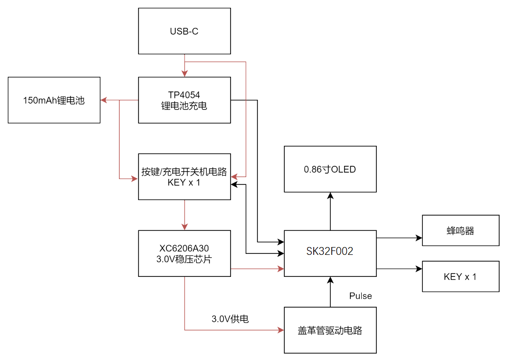
Silico has introduced a low-cost and miniaturized Geiger technology for the detection of ionizing radiation. In this scheme, the cover tube is driven by switching inductor boost, and the signal of the cover tube is converted and calculated by MCU, and then the ionizing radiation intensity in the environment is measured. The scheme is powered by lithium battery, and the driving voltage of the cover tube can be dynamically adjusted to adapt to the decreasing battery voltage. The scheme provides a variety of statistical methods of radiation intensity, such as instantaneous, average and accumulation, as well as auxiliary functions such as hazard alarm. We provide a solution that allows you to quickly achieve the functions required by radiation detection products.
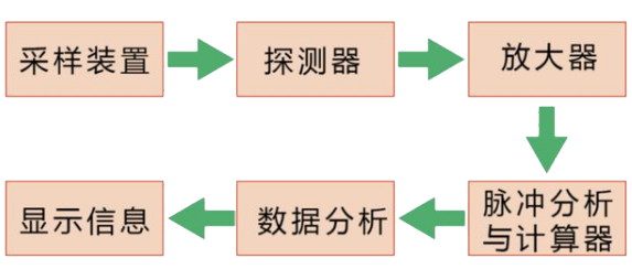
The Geiger Miller counter is a special counting instrument for detecting the intensity of ionizing radiation, using an inflatable tube or chamber as a probe. When the voltage applied to the probe reaches a certain range, each pair of ions produced by the ionization of the ray in the tube can be amplified to produce an electrical pulse of the same size and recorded by a connected electronic device, so the number of rays per unit time can be measured.
The whole product is mainly to drive the Geiger counter, and then record the pulse for data analysis and display.
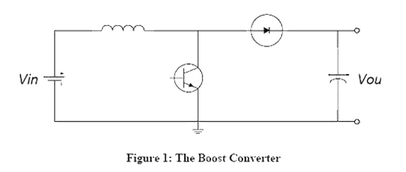
420V boost is the core part: lithium battery 3.5-4.2V to 420V, then the boost ratio to reach about 100, ordinary boost circuit is difficult to achieve low power consumption. This requires lowering the boost ratio, and first consider doubling the voltage (because the current is very small), because the voltage doubling requires capacitors, and three times the voltage is used here.
The principle of the switching DC boost circuit (the so-called boost or step-up circuit) is as follows: during the charging process, the switch is closed (the transistor is on) and the switch (transistor) is replaced by a wire. At this point, the input voltage flows through the inductor. The diode prevents the capacitor from discharging to the ground. Because the input is DC, the current on the inductor increases linearly at a certain rate, which is related to the size of the inductor. As the inductor current increases, some energy is stored in the inductor.
In the process of discharge, when the switch is turned off (the transistor is turned off), the current flowing through the inductor does not immediately change to zero because of the current retention characteristics of the inductor, but slowly changes from the value at the end of charging to zero. The original circuit has been disconnected, so the inductor can only discharge through the new circuit, that is, the inductor begins to charge the capacitor, the voltage at both ends of the capacitor rises, and the voltage is higher than the input voltage.
When charging, the inductor absorbs energy, and the inductor releases energy during discharge. If the capacitance is large enough, a continuous current can be maintained at the output during the discharge. If this on-off process is repeated over and over again, a voltage higher than the input voltage can be obtained at both ends of the capacitor.
● sensor: 48MM Geiger counter
● measurement range: 0.08uSV~50mSV
● measurement accuracy: + 25% based on (_ ^ 137) CS γ
● battery life: 3 to 4 hours (operating current is about 35mA)
● charging time: less than 2 hours
● charging interface: TYPE-C
● size: 15MM*108MM

 Contact us